Dennoch hier ein Bericht über unseren Versuch, der nach einigen Stunden zum Erfolg führte.
Modification of the Drivers from American spoked version to European version
The steam
locos come with a small plastic bag with 4 red replacement inserts for
the wheels that allow to
convert the delivered wheels to the original style . This is not an easy task to be performed and we suggest that
you do not try to do this modification if you are not well skilled. You may loose essential parts, hurt yourself, despair
and / or ruin your loco if you do this modification. Nevertheless here is what we have done and succeeded after a few hours.
Lesen Sie diese Hinweise komplett bevor Sie anfangen !
Read
this first completely before you start !convert the delivered wheels to the original style . This is not an easy task to be performed and we suggest that
you do not try to do this modification if you are not well skilled. You may loose essential parts, hurt yourself, despair
and / or ruin your loco if you do this modification. Nevertheless here is what we have done and succeeded after a few hours.
Lesen Sie diese Hinweise komplett bevor Sie anfangen !
 |
Zunächst,
um den oberen Teil der Lok vor Zerstörung zu
schützen,
entfernen Sie diesen. Hierzu wird die Kappe des mittleren Doms
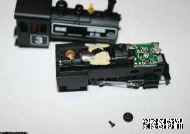
abgenommen und die darunter liegende Schraube gelöst. First , just to protect the shell from any dammage you lift the cap on the dome in the middle of the loco and loosen the screw that is underneath.. |
 |
Nun kann das Oberteil
abgenommen werden. Legen Sie Dom-Kappe und Schraube an einen sicheren
Ort. Now you can lift the body shell . Make sure you put the dome cap and the screw to a safe place ! |
 |
Auf
der Unterseite finden Sie zwei Schrauben, die den Zylinderblock, die
vordere Kupplungshalterung und die Abdeckkappe des Getriebes
am
Platz halten. Lösen Sie diese beiden Schrauben. Ziehen Sie den
Zylinderblock und die Kupplungshalterung nach vorne heraus. Als
nächstes ziehen Sie vorsichtig die vier Pins aus den
Rädern,
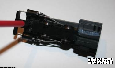
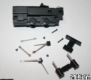
die die Steuerung halten. Verlustgefahr ! Underneath you find two screws that hold the cylinder bar, the coupler and the cover for the axle and gear box together. Unscrew them. Pull the cylinder bar out as well as the front coupler setup. Then pull the four pins from the wheels that hold coupling and driving rods in place. |
 |
Sie
sollten nun ein Teil mehr haben, als auf dem Bild links zu sehen. Wie
zu erwarten, ist ein Pin bereits abgehauen. Wenn Sie um die 100
Lokomotiven am Lager haben, ist das vielleicht nicht ganz so schlimm,
aber dennoch, eine wird nicht wieder ganz herzustellen sein - also
Achtung ! Packen Sie alle Einzelteile an einen sicheren Ort. Now should should have one more piece than what you see on the picture. I at this point missed a pin for the rods. If you happen to have around 100 locos around you it might not really irritate you - but in the end I now have one loco that will never be complete . Maybe we will have a few spares in the future . Please put everything into a safe place. |
 |
Nun
können Sie die Getriebeabdeckung vorsichtig abziehen. Diese
wird
wie im Bild zu sehen, mit 6 Haken gehalten, die leicht brechen
können. Gehen Sie vorsichtig vor. Durch leichtes Verdrehen bei
gleichzeitigem leichten Anheben können Sie die Haken einen
nach
dem anderen lösen. Wenn Sie hier nicht vorsichtig vorgehen
wars
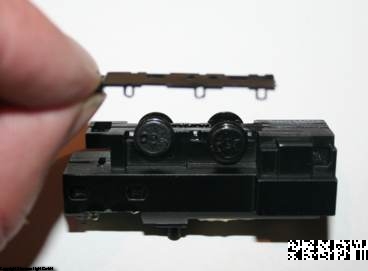
das ! Now you can pull the axle and gearbox cover off. This is a fragile piece and if you are not very carefull, you will break it - As you can see there are 3 little hooks on each side that hold the thing in place. By slightly turning it you can unsnap one after the other. Do this slow, otherwise you are done at this point. |
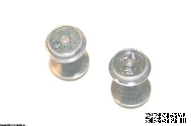 |
Sobald
die Abdeckung weg ist, können die Achsen herausgenommen
werden.
Sie liegen in quadratischen Lagern, die an der Achse festsitzen. Eine
Achse hat ein Zahnrad, merken Sie sich, auf welcher Seite es sitzt. Die
Achsen müssen beim Zusammenbau exakt so wieder eingesetzt
werden.
Nun folgt der wohl schwierigste Teil: Die schwarzen
Kunstoffeinsätze müssen aus den Rädern
entfernt werden.
Ich habe das letztlich dadurch geschafft, dass ich mit einem sehr
spitzen Werkzeug (Verletzungsgefahr) seitlich in die vorhandene Bohrung
gestochen habe, bis ich unter das Teil kam, um es herauszuhebeln. Dabei
geht natürlich der schwarze Einsatz kaputt ! Also damit ist
auch
klar, dass es dann kein Zurück mehr gibt ! After the cover is removed the axles can be taken out. They are sitting in square bearing inserts, One has a gear . Make sure that you put them back in later in the same way as they are now. The picture left shows the next step, most likely the most difficult one. The spoked plastic inserts in the wheels have to get out. I have not found a way to do this without destroying them , so the whole procedure is a one way thing. You can still stop here and just put it back together . |
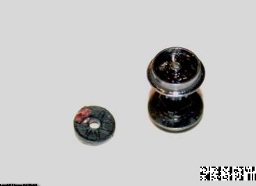 |
Also wenn Sie eine andere
Möglichkeit finden, dann werde ich sie gerne hier mit
anführen ! If you continue, one way that I found is to insert a spiked tool into the existing pinhole of the plastic insert and push it sideways in order to bend the insert out of the wheel. You might try a drill that is just as big as the diameter of the part that sticks out and slowly drill down (drill in a handpiece) until you reach the steel wheel. Then you should be able to reach underneath the plastic and bend it out. This is something where the risk to hurt yourself is very high, so please think first and then start . |
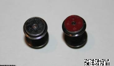 |
Aber
letztlich geht es. Die genaue Ausrichtung der Räder
(Quartering)
ist kein Problem, da die Räder fest auf den Achsen sitzen und
damit die Ausrichtung festliegt. (Mit ausserordentlicher Gewalt
können Sie die Räder auch verdrehen, was Sie hier
besser
nicht tun ) Die neuen Einsätze müssen so in die
Räder
gepresst werden, dass die Nase an den Einsätzen in die
Vertiefung
der Räder passt. Wenn Sie es vor sich haben, sehen Sie was ich
meine. Beachten Sie, dass die offene Seite der Steuerungsbefestigung
aussen liegen muss. Es scheint sinnvoll, die Einsätze mit ein
klein wenig Sekundenkleber zu fixieren. It is possible. Quartering is not an issue as the wheels are not moving (except you use excessive forces - what you avoid) and the inserts have an index . It is hardly visible in the picture above. Once the wheels are in front of you you will instantly see what I mean. Make sure you put the new inserts in so that the opening for the pin sits outside. I think it is a good idea to fix the insert with a small drop of superglue. |
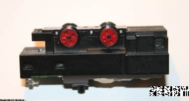 |
Bis
jetzt dürfte etwa eine Stunde vergangen sein - aber wir sind
ja
auch schon weiter. Wie Sie sehen, ist die Abdeckung schon wieder auf
dem Getriebekasten. You may have spent an hour by now - but as you can see the axles are back in the chassis and even the cover has been pushed on to make sure nothing falls out ! |
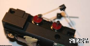 |
Vorsicht - die Pins
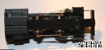
können verloren gehen !!!! Jetzt müssen die Steuerungen wieder eingesetzt werden. Fangen Sie bei den hinteren Rädern an, wo Treib- und Kuppelstange gemeinsam befestigt werden. Die Kuppelstangen sind auf einer Seite mit Detail geätzt. Diese Seite muss nach aussen. Stecken Sie einen Pin durch Treib- und Kuppelstange und pressen Sie ihn in das erste hintere Rad. Drehen Sie nun die vordere Achse so, dass sie gleich steht wie die hintere Achse. Nun können Sie die Kuppelstange auch vorne mit einem Pin befestigen. Wenns nicht gleich beim ersten Mal funktioniert, oder die Achsen nicht richtig eingesetzt sind - na dann nochmal von vorne. Ich hatte auch einige Versuche.... Caution - Risk of pin loss !!!! Now the rods must be put back in place. Start with the rear wheels where both coupler and driver are fixed. Make sure the coupling rod is inserted that the details are visible from outside. Place the pin through coupling and driving rod and push it into the pinhole of the rear wheel. Then proceed to the front. Turn the front axle that it sits exactly like the rear axle , insert the pin through the coupling rod and push it into the pinhole of the front wheel. If it does not work the first time - do not give up. I also had a few .... |
 |
Setzen
Sie den Zylinderblock ein (wissen Sie noch wie der eingesetzt war ?)
und anschliessend den Kupplungshalter. Dann schrauben Sie die beiden
längeren Schrauben, die noch da sind ein, um alles wieder zu
befestigen. Jetzt fehlt nur noch das Lok- Oberteil, welches mit der
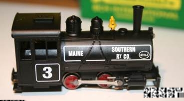
kleinen Schraube befestigt wird - Domkappe drauf - nsert the cylinder bar (remember how it did sit before you started ?) and the front coupler bar and fix everything with the two larger screws that you have put on the side. Put the body shell onto the loco, fix it with the shorter screw and put the dome cap on. |
 |
Fertig
! Done ! |
 |
Spenden sind willkommen, Glückwünsche einfach an mail@minitrains.eu Donations are welcome , greetings can be sent to mail@minitrains.eu |
